Showing posts with label Amateur radio. Show all posts

"Transmitters Q.R.P." article from the "Radio Wsem" magazine, May issue, 1927

Radio Wsem magazine cover
Yet another vintage Soviet magazine with a yellow-red cover and the giant LENIN quote. Not the best possible design ever, let's turn over the cover.

In this article my attention has been drawn to the unusual transmitter with the sounding name "Иккльз-Мени", but the article is very interesting itself as it gives us the ability to imagine the Ham Radio life in several European countries at that time.

I tried to translate it as close to the original, but keep in mind that this article has been translated several times before – Russian translation after the German article and, I suspect that that German publication has been translated from the French source.

Time machine HOWTO: How to win the ancient QRP contest

Some time ago digging the web for information on The Radio Club of Hartford, I came across this article in QST magazine (September issue, 1921). In a nutshell, it is about a QRP contest as it should be - "Do More With Less" and then measure how big this "More" is and how much spare "Less" were used. I read this article briefly: something about some kind of reward, some competitions, the names - not very exciting at first sight, but one remarkable thing caught my attention - The Winner, transmitter that won a first prize. This TX has turned my stereotypes upside down (once again): how should it work? where is a rectifier? grounded plate tank? keying the grid-leak?? I have to investigate, or even better - to make my own, based on this article, design and run such a prehistoric radio on the air!
So, is that contest over? I do not think so, not yet, not for me..


The Radio Club of Hartford (affiliated) recently conducted a very interesting contest in the building of C.W. sets. Several months ago the rules were drawn up and about a dozen members entered. The idea was to devise a simple inexpensive C.W. set of low power, preferably operating from 110 volt lighting current, to supersede the spark coil in the small stations about town. The sharper wave and greater distance with reduced interference made this very desirable, and the Radio Club of Hartford is to be commended for instituting steps that can well be followed by other cities in the reduction of QRM.

One of the members of the club offered a silver loving cup as a grand prize, and in addition there were five 5-watt power tubes offered by the club. The rules called for the award of the prizes to the men having the highest scores on the following basis:

Overall electrical efficiency50%
Workmanship20%
Ingenuity in construction15%
Economy in cost15%
100%

The awards were made at the final meeting of the club before closing for the summer, and eight contestants were on hand with their sets. These were of every imaginable description, but mostly following the general idea of a small base bearing a vertical panel carrying the controls, with the apparatus behind.

Considerable ingenuity was displayed in the source of power. Several of the sets used step-down ("toy") transformers on the 110 volt supply, the low potential current thus obtained being used both to light the filament and to operate a spark coil with regular interrupter, the secondary voltage of which was dropped by a shunt condenser and then fed to the plate of the tube. These sets of course would operate from a storage battery equally well.

It was a condition of the contest that the operating wave length should not exceed 200 meters, and thru faulty design only two sets were able to achieve this - those submitted by J. C. Randall, 1ANQ, Dist. Supt., and F. H. Schnell, 1MO, our Traffic Manager, who is incidentally vice president of the club. Both of these sets, however, were able to get down to 180 meters, altho readings were taken at 200. A phantom antenna was used, consisting of a 12-ohm resistance and a mica condenser of .0005 mfd. capacity, in series with a Jewell thermo-couple ammeter.

Experimental QRP transmitter by UB5DT, "Radio" magazine, April 1967

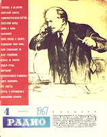
"Radio" magazine cover, April issue, 1967
For those of my friends tube radio builders, who asked me about "Soviet novice transmitter", "XUSSR QRP TX" (as it pronounced in telegraph),"something authentic, but not too complex" etc, such a RIG should be a good choice - easy to build and clearly adjustable design, small amount of widespread parts, a lot of potential operational fun (two possible output sockets, changeable configuration, very uncommon CW note, i believe). And, after all - a frumpish bald telephonist on the cover as a genuine sign of Soviet authenticity.

Experimental QRP Transmitter by I. Tsapiv (UB5DT):

This simple two-stage telegraph transmitter has been developed for a QRP experiments on the amateur HF bands.

The rock bound exciter on the 6П3С (6L6) vacuum tube utilizes circuit known as the "Three-point" (or Tritet in common notation). The crystal controls the frequency of oscillation - 3510kc in this case. Signal output is taken from a separate tuned tank circuit L1C4 in the plate circuit of exciter; this tank should be tuned to 3510kc or 7020kc.

The second stage on the 6П7С (6BG6) tube acts as an amplifier or frequency multiplier (doubler or tripler) depends on an inductance of the L2 coil and bias voltage on the signal grid of this tube.
QRP Transmitter
If you would like to use this transmitter on 80m band as well as on 40m with a noticeable lowered power, you have to connect an antenna to the "A1" connector and pull the amplifier tube (6BG6) out from the socket. For the general power output on 7020kc and QRP operations on 14040kc and 21060kc that tube has to be back and antenna switched to the "A2" output connector.
Measured Power:
frequency single stage (6П3С) both stages
3510kc 8 W -
7020kc 3 W 18 W
14040kc - 6...8 W
21060kc - 1,5...2,5 W

Several interesting QSO's  has been obtained using this transmitter in October 1966. For example, UA0MX and K2AGU on 14Mc, and F9MC on 21Mc with a power level as low as 1.7 Watt.

6N7 Tube QRP Power Amplifier - One Rainy Day DIY Project

QRP 6N7 Tube Amplifier
Once upon a time I'd decided to join a Big Guns Gang and made a Super-Duper Powerful Vacuum Tube QRP amplifier for my 800mW QRPP homebrew telegraph vacuum tube transceiver "3T" (I promise to write a separate article or two about this three tube transceiver project later). It was not an easy decision to me because for that legendary time I'd almost a year used the QRPP power of less than a watt, but there was a rainy spring day, I've called CQ again and again without any takers and, at very last, somebody took over my only rock bound frequency. "That's all" - I said - "Enough!" ..and turned on my Soldering Iron.
Let me describe the scheme. Grounded-Grid design has been chosen because it is simple, easy to matching to coaxial impedance, provides the necessary level of amplification and typically requires no neutralization. After several experiments with triodes and double triodes I'd chose a 6N7S (6H7C) valve - Russian glass shaped version of well known 6N7 vacuum tube. I know that there was a 6N7G and 6N7GT American glass tubes, but as I heard these ones was not as common as metal 6N7.

Building A Vintage 1929 Style Transmitter - Best HOWTO

Yes, Best HOWTO Ever, but not mine - hats off to Steve VE7SL. I've found this great article reading the Glowbugs mail list and I have to post it here because this article is a pure gem. Even if you never did it before, after the reading of that article you can to, you have to make your first TNT or Hartley transmitter and trust me - it is only first steps into the amazing world of glowing history!

VE3DVK VINTAGE TPTG Push-Pull TRANSMITTER
BUILDING A 1929 VINTAGE TNT TRANSMITTER

Quote:
"After some research into the 1929 transmitter style, it became apparent that most amateurs of the period were using either a Tuned-Plate-Tuned-Grid (TPTG), a Hartley oscillator or a Tuned-Not-Tuned (TNT) design. I can well imagine the countless late night 160m AM QSO's of the day discussing and arguing the virtues of each amateur's chosen design. Eventually I decided on the TNT, a simpler off-shoot of the TPTG design."

READ COMPLETE ARTICLE AND DO IT YOURSELF! >>
Reblog this post [with Zemanta]

Junkyard Warz Novelty Transmitter by W9QZ

Several month ago I found a great, probably most artistic Glowbugs Radio homebrewer in the WEB - Rick Weber, W9QZ. I've been very impressed, downloaded some beautiful photos of those stylish Rick's HAM-Radio artefacts and, naturally, forget to check this page again - it was my mistake. Take this:

JunkYard D.I.Y. Transmitter

Rick:
"Junkyard Warz Novelty Project. This is a working Hartley transmitter I built with all non-radio components except for one 027 vacuum tube."
Visit W9QZ Vintage Gears and enjoy the fire of these FireBottles (not only fire - you can find some bottles turned  into HF insulators in the Lab of Great Steampunk Wizard, W9QZ)
Reblog this post [with Zemanta]

Second Life of Dead MFM Hard Drives - Iambic Paddle

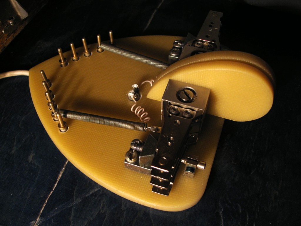
Homebrew Iambic Paddle Just finished my first in life "Instructable" at the D.I.Y. host site instructables. It is short sketch about Iambic Paddle which has been made using a spare parts from the dead MFM HDD drive. I got a lot of fun posting to that site, and I think that it should be good idea to post more detailed article here. Frankly, this homebrew project is not a Pure Glowing Bug, but I'm not so puristic today.
Well, let me explain - why I decided to use HDD heads as a levers in this Iambic Paddle Project. For many years I've collected computer spare parts for no reason, just because I have a big, nearly endless Junk Box and it was impossible to me to throw such high-tech toys in the trash. But one morning I found that my Junk Box is full and The Time of Trash Bags has come. It was a hard work, but under the tons of debris I found the treasure - my first homemade Z80 Sinclair Spectrum and five old 5 inch MFM hard drives from my second computer.
As you remember, these drives was a big rounded shaped boxes, ideal as a chassis for any homemade electronic projects, tube glowbugs as well as solid state stuff. Another interesting things - powerful electromotor and magnetic cylinders itself, thick shiny discs which are so usable as a dial or scale part, looked much better than a CD in this role. And last but not least - yes, precision bearings on the easy to mount axis in magnetic head's block. What a beautiful hardware! When I opened and totally disassembled these hard drives, I realized that I literally had a very new telegraph key, usual one lever, dual lever iambic paddle or even straight key - not so important, it is easy to make any kind of telegraph manipulator using these nice spare parts. Watch this video demonstrating a working Iambic Paddle and take a look at step by step constructing process here:

Big Nick and the Cydecos - Glowbugs Radio Hide-And-Seek

KC9KEP's ARRL 1941 7-Tube Superheterodyne Homebrew Radio Today I decided to become (at very last) a real blogger and to invite some celebrities as a trendy stuff. But as it turned out, neither Madonna nor Britney Spears did not make the tube radios, Arnold Schwarzenegger is possible and would do, but too busy at work, and Michael Jackson .. Okay, let's not about sad - the result of my quest was a brilliant success:

6P3 (6П3) Beam Power Tetrode

6P3, 6P3S, 6P3S-E vacuum tubes
6L6 vacuum tube has been introduced by Radio Corporation of America in July 1936 and since 1937 it began to be produced in the USSR on equipment provided by RCA. For the first time it was usual metal 6L6 , but later was chosen glass bulb design in order to avoid overheating, so just before the WWII tube factories started to produce 6P3 (6П3) valves (left on photo), which was actually Soviet version of 6L6-GB tube.
After the forties, design has been changed (center tube on the photo) and the new one got additional "S" mark, which meant "Oktal" according to the post-war standard specification. There was some modifications such as 6P3S-E (6П3С-Е) (at the right on the photo) and 6P3S-EV (6П3С-ЕВ). I heard a lot of controversial stories about these extra letters, but according to the GOST it is Durability (E) and Reliability (V), so 6P3S-EV is just a high mechanical quality version of general 6P3S (6П3С) with warranted lifetime, probably military or industrial purpose. As for claimed electrical parameters, these 6P3S-E (6П3С-Е) and 6P3S-EV (6П3С-ЕВ) tubes has less current and voltage deviations than common 6P3S but according to my subjective opinion WWII 6P3 tube was a best performer in this family.
Naturally, 6P3 tube has always been one of the most popular in a variety of radio enthusiasts, it can be found in a Hi-End audio amplifier as well as in a HAM-Radio transmitter. BTW, not only HAM-Radio - it was and it is The Legendary Tube of the xUSSR Radio Pirates. Every Pirate Newbie starts with "The Whistle" - classical simple one 6P3S tube AM transmitter and so remarkable that a main web site of these guys is http://6P3S.ru

USSR HAM-Radio CallBook in 1926

I just found a very interesting paper - a complete list of all transmitting amateur radio stations in 1926 in the USSR, club stations, as well as personal ones. It is remarkable, that the frequencies and power levels of club stations are selected in such a way that ensures reliable traffic between distant regions and Moscow - the farther station from center, the higher its power and shorter its wavelength. And another note - individuals had managed to use different wavelengths, so it was not too easy to contact each other that times.

6P7S (6П7С) Sweep Tube

6P7S Sweep Tube
6P7S (6П7С) TV sweep tubes, as their western sisters 6BG6 was used as a horizontal driver in some early black'n'white TV sets. In fact, this tube is not a direct 6BG6 clone, it is an octal modification of G-807 tube, which one was soviet clone of famous 807. Interesting, that both 6P7S and 6BG6 tubes has the same pinout and nearly the same characteristics.
I heard that 6BG6 valves sounds much better than 6P7S in audio devices and that 6P7S is worthless audio tube, much worse than G-807 and 6P3S ones. At the other hand, I heard that 6P7S has a beautiful clear treble sound, much better than 6P3S. I'm not quite sure - it's just rumours.
As for me, 6P7S is a good choice if you have to put something more powerful than 6P3S (6L6) into the octal socket. Strangely, but 6P7S tubes are rarely used in HAM-radio (compared with G-807 and 6P3S).

GK-71 (ГК-71) Power Pentode

GK-71 (ГК-71) POWER RF PENTODE
GK-71 (ГК-71) is a somewhat similar (but not the same) to the famous 813 by RCA. There was another soviet replica of RCA 813 - GU-13.
GK-71 (ГК-71) has a narrower frequency range and a slightly less gain than, say, GU-13 tube, but there are some advantages - it was dirt-cheap and has a terrific endurance (resultant of massive graphite anode block and durable heavy-duty construction).
Possible, GK-71 was the most popular power tube in the AM pirate's anti-society. I'm not quite sure, I have no statistical data of pirate's preferences, but all of my unsocial friends was a GK-71 boosters.
At the other hand, this power pentode was a "Full Legal Limit" tube to the HAM Radio amateurs and one GK-71 final have to be approved without power measuring. I've heard rumours about the one GK-71 tube multy-megawatters, asbestos glove for quick tube replacement etcetera, but reality is slightly less wondrous - 350 watts from one tube without overheating, up to 450-500 watts if you are out-and-outer.