Showing posts with label qrp transmitter. Show all posts

"Transmitters Q.R.P." article from the "Radio Wsem" magazine, May issue, 1927

Radio Wsem magazine cover
Yet another vintage Soviet magazine with a yellow-red cover and the giant LENIN quote. Not the best possible design ever, let's turn over the cover.

In this article my attention has been drawn to the unusual transmitter with the sounding name "Иккльз-Мени", but the article is very interesting itself as it gives us the ability to imagine the Ham Radio life in several European countries at that time.

I tried to translate it as close to the original, but keep in mind that this article has been translated several times before – Russian translation after the German article and, I suspect that that German publication has been translated from the French source.

Time machine HOWTO: How to win the ancient QRP contest

Some time ago digging the web for information on The Radio Club of Hartford, I came across this article in QST magazine (September issue, 1921). In a nutshell, it is about a QRP contest as it should be - "Do More With Less" and then measure how big this "More" is and how much spare "Less" were used. I read this article briefly: something about some kind of reward, some competitions, the names - not very exciting at first sight, but one remarkable thing caught my attention - The Winner, transmitter that won a first prize. This TX has turned my stereotypes upside down (once again): how should it work? where is a rectifier? grounded plate tank? keying the grid-leak?? I have to investigate, or even better - to make my own, based on this article, design and run such a prehistoric radio on the air!
So, is that contest over? I do not think so, not yet, not for me..


The Radio Club of Hartford (affiliated) recently conducted a very interesting contest in the building of C.W. sets. Several months ago the rules were drawn up and about a dozen members entered. The idea was to devise a simple inexpensive C.W. set of low power, preferably operating from 110 volt lighting current, to supersede the spark coil in the small stations about town. The sharper wave and greater distance with reduced interference made this very desirable, and the Radio Club of Hartford is to be commended for instituting steps that can well be followed by other cities in the reduction of QRM.

One of the members of the club offered a silver loving cup as a grand prize, and in addition there were five 5-watt power tubes offered by the club. The rules called for the award of the prizes to the men having the highest scores on the following basis:

Overall electrical efficiency50%
Workmanship20%
Ingenuity in construction15%
Economy in cost15%
100%

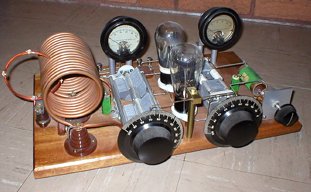
The awards were made at the final meeting of the club before closing for the summer, and eight contestants were on hand with their sets. These were of every imaginable description, but mostly following the general idea of a small base bearing a vertical panel carrying the controls, with the apparatus behind.

Considerable ingenuity was displayed in the source of power. Several of the sets used step-down ("toy") transformers on the 110 volt supply, the low potential current thus obtained being used both to light the filament and to operate a spark coil with regular interrupter, the secondary voltage of which was dropped by a shunt condenser and then fed to the plate of the tube. These sets of course would operate from a storage battery equally well.

It was a condition of the contest that the operating wave length should not exceed 200 meters, and thru faulty design only two sets were able to achieve this - those submitted by J. C. Randall, 1ANQ, Dist. Supt., and F. H. Schnell, 1MO, our Traffic Manager, who is incidentally vice president of the club. Both of these sets, however, were able to get down to 180 meters, altho readings were taken at 200. A phantom antenna was used, consisting of a 12-ohm resistance and a mica condenser of .0005 mfd. capacity, in series with a Jewell thermo-couple ammeter.

Experimental QRP transmitter by UB5DT, "Radio" magazine, April 1967

"Radio" magazine cover, April issue, 1967
For those of my friends tube radio builders, who asked me about "Soviet novice transmitter", "XUSSR QRP TX" (as it pronounced in telegraph),"something authentic, but not too complex" etc, such a RIG should be a good choice - easy to build and clearly adjustable design, small amount of widespread parts, a lot of potential operational fun (two possible output sockets, changeable configuration, very uncommon CW note, i believe). And, after all - a frumpish bald telephonist on the cover as a genuine sign of Soviet authenticity.

Experimental QRP Transmitter by I. Tsapiv (UB5DT):

This simple two-stage telegraph transmitter has been developed for a QRP experiments on the amateur HF bands.

The rock bound exciter on the 6П3С (6L6) vacuum tube utilizes circuit known as the "Three-point" (or Tritet in common notation). The crystal controls the frequency of oscillation - 3510kc in this case. Signal output is taken from a separate tuned tank circuit L1C4 in the plate circuit of exciter; this tank should be tuned to 3510kc or 7020kc.

The second stage on the 6П7С (6BG6) tube acts as an amplifier or frequency multiplier (doubler or tripler) depends on an inductance of the L2 coil and bias voltage on the signal grid of this tube.
QRP Transmitter
If you would like to use this transmitter on 80m band as well as on 40m with a noticeable lowered power, you have to connect an antenna to the "A1" connector and pull the amplifier tube (6BG6) out from the socket. For the general power output on 7020kc and QRP operations on 14040kc and 21060kc that tube has to be back and antenna switched to the "A2" output connector.
Measured Power:
frequency single stage (6П3С) both stages
3510kc 8 W -
7020kc 3 W 18 W
14040kc - 6...8 W
21060kc - 1,5...2,5 W

Several interesting QSO's  has been obtained using this transmitter in October 1966. For example, UA0MX and K2AGU on 14Mc, and F9MC on 21Mc with a power level as low as 1.7 Watt.

TNT Uncovered - Flea-Power (QRP) Telegraph Transmitter in the Pilot Radio's "Radio Design" magazine, 1930's

Pilot Radio And Tube Corporation, trade mark

I found this article in the Lloyds Dipsy Dumpster - site, where you can find a lot of rare vintage radio articles, manuals and data sheets.

It is remarkable, that "Pilot Radio & Tube Corporation", well known as a manufacturer of the great Super-Wasp receivers, was a publisher of a Ham-Radio literature, handbooks and magazines, as well as many of early radio manufacturing companies. As for me, I like that sort of advertising much more, than modern spam in my mailbox and if it would be possible, it should be a nice choice to make this QRP transmitter using a native Pilot's parts only.

Anyway, when I've read this article, one interesting fact has drawn my attention - I can recognize the TNT when I see a TNT design, but in the text this transmitter has been described as a TPTG.. Moreover, there is a grid capacitor on the assembles view, but with a opposite description below: "condenser is not needed". So, in the article we can see that mysterious moment, when as the chrysalis becomes the butterfly, TPTG transmitter was transformed into a trendy TNT.


Building A Vintage 1929 Style Transmitter - Best HOWTO

Yes, Best HOWTO Ever, but not mine - hats off to Steve VE7SL. I've found this great article reading the Glowbugs mail list and I have to post it here because this article is a pure gem. Even if you never did it before, after the reading of that article you can to, you have to make your first TNT or Hartley transmitter and trust me - it is only first steps into the amazing world of glowing history!

VE3DVK VINTAGE TPTG Push-Pull TRANSMITTER
BUILDING A 1929 VINTAGE TNT TRANSMITTER

Quote:
"After some research into the 1929 transmitter style, it became apparent that most amateurs of the period were using either a Tuned-Plate-Tuned-Grid (TPTG), a Hartley oscillator or a Tuned-Not-Tuned (TNT) design. I can well imagine the countless late night 160m AM QSO's of the day discussing and arguing the virtues of each amateur's chosen design. Eventually I decided on the TNT, a simpler off-shoot of the TPTG design."

READ COMPLETE ARTICLE AND DO IT YOURSELF! >>
Reblog this post [with Zemanta]

Evergreen Exciter for the Special Night

Magic Eye Transmitter
Several days ago I listened to the completely empty ten meters band. There was a lot of noises, quiet CB chewing and nothing else.
Suddenly I heard a slow, quiet, but very clear telegraph code, resembling W1AW QST. I have not heard the beginning, but wrote all heard:

Straight Key Night M.O.P.A. Transmitter

SKN Operating Position
After reading a lot of ancient QSTs, ARRL and Jones Handbooks plus e-mail conversations with my friend, Louis VE3AWA about American depression-era style rig design, I decided to build a classic breadboard transmitter in time for Straight Key Night.

Well, breadboard MOPA seemed like a very interesting idea, it was absolutely unusual for me - I never used wooden chassis (breadboard) without any metal shielding before. Second problem - I'd started this project too late, for only one week before the SKN.
To my surprise, I got my firefly finished and fired-up during Straight Key Night! Without any success - there was no SKN participants over here. But what done is done and I was so glad to hear many "loud and clear" signal reports and heartwarming words from EU CW stations. Maybe next SKN, VE and W stations will make a sked to work UU1CC.