Experimental QRP Transmitter by I. Tsapiv (UB5DT):
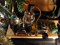
This simple two-stage telegraph transmitter has been developed for a QRP experiments on the amateur HF bands.The rock bound exciter on the 6П3С (6L6) vacuum tube utilizes circuit known as the "Three-point" (or Tritet in common notation). The crystal controls the frequency of oscillation - 3510kc in this case. Signal output is taken from a separate tuned tank circuit L1C4 in the plate circuit of exciter; this tank should be tuned to 3510kc or 7020kc.
The second stage on the 6П7С (6BG6) tube acts as an amplifier or frequency multiplier (doubler or tripler) depends on an inductance of the L2 coil and bias voltage on the signal grid of this tube.

If you would like to use this transmitter on 80m band as well as on 40m with a noticeable lowered power, you have to connect an antenna to the "A1" connector and pull the amplifier tube (6BG6) out from the socket. For the general power output on 7020kc and QRP operations on 14040kc and 21060kc that tube has to be back and antenna switched to the "A2" output connector.
Several interesting QSO's has been obtained using this transmitter in October 1966. For example, UA0MX and K2AGU on 14Mc, and F9MC on 21Mc with a power level as low as 1.7 Watt.
Measured Power:
| frequency | single stage (6П3С) | both stages |
|---|---|---|
| 3510kc | 8 W | - |
| 7020kc | 3 W | 18 W |
| 14040kc | - | 6...8 W |
| 21060kc | - | 1,5...2,5 W |
Several interesting QSO's has been obtained using this transmitter in October 1966. For example, UA0MX and K2AGU on 14Mc, and F9MC on 21Mc with a power level as low as 1.7 Watt.
Coil Data:
| # | frequency, kc | winding type | coil form | turns | wire |
|---|---|---|---|---|---|
| L1 | 3510...7020 | Single-layer | 30mm | 15 | ø 0,5mm |
| L2 | 7020 | Single-layer | 20mm | 31 | ø 0,35mm |
| L2 | 14040 | Air-wound, 50mm long | 30mm | 11 | ø 1,0mm |
| L2 | 21060 | Air-wound, 35mm long | 30mm | 6,5 | ø 1,0mm |


4 comments :
Hello !
The 6L6 is just a 6BG6G, with the anode connection carried at the socket. It allows, therefore, a cleaner layout when it comes to delivering the RF to the PA tube. What do you think ? My main TX is a MOPA, actually, with VFO + 2 aperiodic buffers added before the driver/multiplier. Actually is general coverage from 1.6 up to 15 Mhz, and with some improvements in the resonant circuits, I am planning to go up to 28 MHz. It is so stable and chirpless that I don't need modern gear. The VFO is made by a triode, and has both band switching and control grid keying. The 7MHz 4th harmonic on 28 MHz is very clean and stable. My MOPA is really not a compromise ad allows me radio traffic in CW with, practically, no any limitations!
73 de Cristiano, IZ3CQI
Hi Cristiano and thank you for the comment.
I shouldn't say that, for example, 6BG6 is a less powerful version of 807 or, as you said, slightly different version of 6L6. It is not quite true - those tubes has a different purpose, construction, characterisics and so on. Sure, they are very close to each other, but not the similar ones.
It would be really interesting to read an article on your MOPA, to see the photo set or even the video about it. If you'll decide to write such an article, please drop a link here.
73! UU1CC
YC0LOG,73,
nice using cccp tubes,and RCA tubes or JRC tubes.but not china made
Post a Comment